Diagonalized Upwind Navier Stokes Code
Tutorial Page
3. MULTI-BLOCK GRIDS
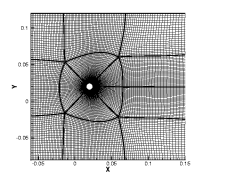
Before you start using the DUNS code, you need to understand one or two things about multi-block grids and solutions. Geometries are typically defined by surfaces, which indicate the boundary between the computed region and the non-computed region. Physically, these surfaces represent, for instance, the surface of an airfoil, the walls of a combustion chamber, the inlet or exit plane in duct flow, etc. For example, imagine a cylinder in a duct, as represented in figure 1. This geometry can be described by five surfaces. The first surface is the inlet plane upstream of the cylinder. The second surface is the exit plane far downstream of the cylinder. The two walls on either side of the cylinder represent two more surfaces, and the cylinder itself represents a fifth surface.

Multi-block grids in terms of the DUNS code have fairly specific meaning. A multi-block grid takes a given domain and breaks it up into N number of structured blocks. Each block is surrounded by from zero to four other blocks (again, please refer to the figure.) For two-dimensional grids, each point within a block is identified by an (i,j) pair, (similar to an (x,y) pair on a cartesian coordinate system). The i=1 plane is identified as the west boundary of the block, the i=imax plane is identified as the east boundary, and so on. For the example in Figure 1, the domain is divided into 18 separate blocks.
For true multi-block grids, blocks that border each other have a one-to-one
correspondence for points on that border. That is, the location of any point
on the boundary surface for the one block corresponds exactly to a point on
the surface of the other block. Describing how the blocks match up is called
the connectivity of the grid. For the DUNS code, the grid data is
stored as an unformatted file in plot3d format in duns.grid,
or as an ASCII file, and the connectivity
information is stored in an ASCII file duns.conn, as is described
below. The specific formats for these files are described in detail
under input files, and often represent the most complex part about setting up
a CFD problem (depending, of course, on the complexity of the geometry).
Next Previous Contents